Active Filter Design Techniques
🎯 What you'll get
MODULE 1 — Introduction to Active Filters
1.1 What is a Filter?
- Purpose of filtering
- Desired vs unwanted frequencies
- Frequency-selective circuits
- Analogue vs digital filters
1.2 What is an Active Filter?
- Passive filter
- Active filter
- Advantages of active filters
- Limitations of active filters
1.3 Components of an Active Filter
- Resistors
- Capacitors
- Op-amps
- Feedback network
1.4 Applications
- Audio
- Sensor signal conditioning
- ADC anti-aliasing
- Instrumentation
- Communications
- Automotive electronics
- Power electronics
- Control systems
Online activity
Students identify filter applications in real electronic systems.
MODULE 2 — Filter Terminology & Specifications
Students learn the terminology used when specifying a real filter.
Topics
- Passband
- Stopband
- Transition band
- Cut-off frequency
- Centre frequency
- Bandwidth
- Attenuation
- Gain
- Roll-off
- Selectivity
Important parameters
- -3 dB frequency
- Q factor
- Damping factor
- Insertion loss
- Stopband rejection
Practical exercise
Given a filter specification, students identify:
Passband → Stopband → Transition region → Required attenuation
MODULE 3 — Frequency Response Fundamentals
3.1 Frequency Response
- Magnitude response
- Phase response
3.2 Bode Plots
- Frequency axis
- dB scale
- Phase plot
- Logarithmic frequency
3.3 Decibels
- Voltage gain in dB
- Power gain in dB
- Gain/attenuation
3.4 Poles & Zeros
- Introduction to poles
- Introduction to zeros
- Effect on magnitude
- Effect on phase
Online simulation
Students create a Bode plot for a simple RC network and identify its cut-off frequency.
MODULE 4 — First-Order Active Filters
4.1 First-Order Low-Pass
- Circuit topology
- Transfer function
- Cut-off frequency
- Gain
4.2 First-Order High-Pass
- Circuit topology
- Frequency response
- Gain
4.3 Buffering
- Voltage follower
- Loading effects
4.4 Non-Inverting Active Filter
Design exercise
Specification:
Design an active low-pass filter with a 1 kHz cut-off frequency and a gain of 2.
Students:
- Select topology.
- Calculate component values.
- Build circuit in SPICE.
- Run AC sweep.
- Generate Bode plot.
- Verify the design.
MODULE 5 — Second-Order Filter Fundamentals
Second-order filters are the foundation of practical active filter design.
Topics
- Second-order response
- Natural frequency
- Damping
- Q factor
- Resonance
- Peaking
Standard form
Students learn how the second-order transfer function relates to:
- Natural frequency
- Q
- Gain
Response shapes
- Overdamped
- Critically damped
- Underdamped
Simulation
Students change Q and observe the response.
MODULE 6 — Second-Order Low-Pass Filters
Topics
- Second-order low-pass topology
- Gain
- Cut-off frequency
- Q factor
- Component selection
Design parameters
- R1
- R2
- C1
- C2
- Op-amp gain
Online design exercise
Design a:
2nd-order 2 kHz low-pass filter
with specified:
- Gain
- Q
- Component constraints
MODULE 7 — Second-Order High-Pass Filters
Topics
- Second-order high-pass topology
- Cut-off frequency
- Q factor
- Gain
- Phase response
Design exercise
Design:
2nd-order high-pass filter
with a specified:
- Cut-off frequency
- Gain
- Q
SPICE verification
Compare:
Calculated response vs simulated response
MODULE 8 — Band-Pass Filters
8.1 What is a Band-Pass Filter?
- Lower cut-off
- Upper cut-off
- Centre frequency
- Bandwidth
8.2 Active Band-Pass Topologies
- Cascaded HP + LP
- Multiple-feedback band-pass
- State-variable band-pass
Parameters
- Centre frequency
- Bandwidth
- Q
- Gain
Online design project
Design a filter passing:
900 Hz–1.1 kHz
while attenuating frequencies outside the desired band.
MODULE 9 — Band-Stop & Notch Filters
Topics
- Band-stop operation
- Notch filters
- Centre frequency
- Notch depth
- Bandwidth
Applications
- Mains-frequency rejection
- Interference removal
- Sensor systems
- Audio
- Instrumentation
Practical project
50/60 Hz Notch Filter
Students design a notch filter to remove mains interference from a simulated sensor signal.
They investigate:
- Notch frequency
- Notch depth
- Q
- Component tolerance
MODULE 10 — Filter Approximation & Response Types
This is where the course moves from basic circuit design into professional filter design.
Butterworth
- Maximally flat magnitude response
- Passband behaviour
- Applications
Chebyshev Type I
- Passband ripple
- Sharper transition
Chebyshev Type II
- Stopband ripple
- Passband characteristics
Bessel
- Phase characteristics
- Group delay
- Waveform preservation
Elliptic
- Passband ripple
- Stopband ripple
- Very sharp transition
Comparison
Students investigate:
| Filter | Key characteristic |
|---|---|
| Butterworth | Flat magnitude response |
| Chebyshev I | Faster transition, passband ripple |
| Chebyshev II | Stopband ripple |
| Bessel | Good phase/group-delay behaviour |
| Elliptic | Very sharp transition |
MODULE 11 — Filter Order & Cascading
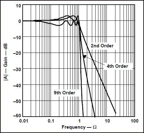
Why increase filter order?
- Sharper roll-off
- Better stopband attenuation
Topics
- First-order
- Second-order
- Fourth-order
- Sixth-order
- Higher-order filters
Cascading stages
Example:
2nd-order stage + 2nd-order stage = 4th-order filter
Practical considerations
- Gain distribution
- Q distribution
- Component interaction
- Op-amp limitations
Design exercise
Design a:
4th-order Butterworth low-pass filter
and verify its attenuation.
MODULE 12 — Sallen-Key Filters
One of the most important practical active-filter topologies.
Topics
- Sallen-Key architecture
- Unity-gain Sallen-Key
- Non-inverting Sallen-Key
- Low-pass
- High-pass
Design parameters
- R values
- C values
- Gain
- Q
- Cut-off frequency
Advantages
- Simple design
- Low component count
- Easy implementation
Limitations
- Q limitations
- Component sensitivity
- Op-amp limitations
Online simulation
Students design several Sallen-Key filters and compare their responses.
MODULE 13 — Multiple-Feedback Filters
Topics
- Multiple-feedback topology
- Low-pass
- High-pass
- Band-pass
Advantages
- High-Q applications
- Compact implementation
- Useful band-pass designs
Limitations
- Component sensitivity
- Gain dependence
- Design complexity
Design exercise
Create a:
High-Q band-pass filter
for a specified centre frequency.
MODULE 14 — State-Variable Filters
Topics
- State-variable architecture
- Integrators
- Summing amplifier
- Multiple outputs
Simultaneous outputs
- Low-pass
- Band-pass
- High-pass
Advantages
- Independent tuning
- Multiple outputs
- Good control of Q
Applications
- Instrumentation
- Audio
- Signal processing
Virtual experiment
Students adjust one parameter and observe how:
- Centre frequency
- Q
- Gain
change.
MODULE 15 — Twin-T & Active Notch Filters
Topics
- Twin-T network
- Passive notch
- Active notch
- Q improvement
- Notch depth
Applications
- Mains rejection
- Sensor interference
- Audio systems
- Instrumentation
Practical simulation
Inject:
50 Hz + 1 kHz signal
and demonstrate removal of the 50 Hz component.
MODULE 16 — High-Q Active Filters
Topics
- What is Q?
- High-Q response
- Resonance
- Stability concerns
- Component sensitivity
Applications
- Communications
- Audio
- Instrumentation
- Frequency-selective systems
Design exercise
Design a filter with:
High Q + narrow bandwidth
and investigate its sensitivity to component variation.
MODULE 17 — Op-Amp Selection for Active Filters
This is essential for practical filter design.
Students learn that an ideal op-amp model isn't enough for a real filter.
Op-amp parameters
- Gain-bandwidth product
- Slew rate
- Input offset voltage
- Input bias current
- Input/output voltage range
- Output current
- Noise
- Common-mode range
GBW Requirement
Students learn why the op-amp must have sufficient bandwidth relative to the filter's operating frequency.
Slew Rate
Understand how insufficient slew rate causes waveform distortion.
Online simulation
Compare:
Ideal op-amp vs limited-bandwidth op-amp
inside the same filter.
MODULE 18 — Stability & Phase
Topics
- Phase shift
- Feedback
- Stability
- Phase margin introduction
- Oscillation
Active-filter stability
- High-Q filters
- Op-amp phase response
- Feedback interaction
Practical investigation
Students increase filter Q and observe how the real op-amp affects stability.
MODULE 19 — Component Selection & Tolerances
Real components are not exact.
Topics
- Resistor tolerance
- Capacitor tolerance
- Temperature coefficient
- Component availability
Sensitivity
- Frequency sensitivity
- Q sensitivity
- Gain sensitivity
Monte Carlo simulation
Students simulate:
100 component variations
and observe the spread in:
- Cut-off frequency
- Gain
- Q
This is particularly valuable in an online engineering course.
MODULE 20 — Noise in Active Filters
Noise sources
- Resistor thermal noise
- Op-amp voltage noise
- Op-amp current noise
- Sensor noise
- Supply noise
Filter vs noise
- Filtering unwanted frequencies
- Noise bandwidth
- In-band noise
Practical exercise
Students compare:
Noisy signal → Filter → Output
and calculate/observe the improvement.
MODULE 21 — Loading & Impedance Effects
Topics
- Input impedance
- Output impedance
- Loading
- Buffering
Why active filters help
- Isolation between stages
- Gain
- High input impedance
- Low output impedance
Practical simulation
Compare:
Passive filter → Load
vs
Buffered active filter → Load
and observe the difference.
MODULE 22 — Filter Design for ADC Inputs
A very important bridge between analogue electronics and embedded systems.
Topics
- ADC input requirements
- Anti-aliasing
- Noise reduction
- Signal bandwidth
- Sampling frequency
Design flow
Sensor → Active Filter → ADC → MCU
Example
Given:
ADC sampling rate = 10 kHz
students design an appropriate analogue low-pass filter.
Design considerations
- Cut-off frequency
- Filter order
- Stopband attenuation
- Op-amp bandwidth
- Noise
MODULE 23 — Active Filters for Sensor Signal Conditioning
Applications
- Temperature
- Pressure
- Current
- Voltage
- Accelerometers
- Strain gauges
Signal-conditioning chain
Sensor → Gain → Filter → Level shift → ADC
Practical project
Design an active filter for a simulated temperature sensor.
MODULE 24 — Active Filters in Power Electronics
This makes the course particularly relevant to advanced electronics students.
Applications
- Current sensing
- Voltage sensing
- DC-link measurement
- Feedback loops
- Switching-noise attenuation
- Gate-driver sensing
- Power-converter control
Topics
- Switching-frequency noise
- Low-pass sensing filters
- Control-loop filtering
- Differential sensing
Example
Design an analogue filter to extract the average value from a switching waveform.
MODULE 25 — Filter Design Using SPICE
This should be a major practical module.
Students learn
- Creating schematics
- Selecting op-amps
- AC sweep
- Transient analysis
- Parameter sweep
- Monte Carlo analysis
- FFT
- Bode plots
Simulations
Students simulate:
- Low-pass
- High-pass
- Band-pass
- Notch
- 4th-order filter
- High-Q filter
MODULE 26 — Time-Domain vs Frequency-Domain Analysis
Frequency domain
- Bode plot
- Gain
- Phase
- Bandwidth
Time domain
- Step response
- Impulse response
- Transient response
Relationship between them
Students investigate how filter frequency response affects a time-domain waveform.
Practical exercise
Apply:
- Square wave
- Sine wave
- Pulse
to the same filter and observe the outputs.
MODULE 27 — FFT & Spectrum Analysis
What is FFT?
- Time domain
- Frequency domain
- Spectrum
Topics
- Fundamental frequency
- Harmonics
- Noise
- Sampling
- Aliasing introduction
Online simulation
Students apply a distorted waveform to a filter and use FFT to identify unwanted frequency components.
MODULE 28 — Filter Troubleshooting
Students receive intentionally faulty filter designs.
Fault examples
- Wrong resistor value
- Wrong capacitor value
- Incorrect op-amp connection
- Incorrect gain
- Insufficient GBW
- Saturated output
- Excessive Q
- Loading
- Component tolerance
Troubleshooting method
Specification → Simulation → Measurement → Compare → Diagnose → Correct
MODULE 29 — Practical Active Filter Design Workflow
Students learn a professional design process.
Step 1
Define the specification.
Step 2
Select filter type.
Step 3
Determine required order.
Step 4
Select topology.
Step 5
Calculate component values.
Step 6
Select the op-amp.
Step 7
Run SPICE simulation.
Step 8
Perform tolerance analysis.
Step 9
Check noise.
Step 10
Check transient response.
Step 11
Optimise components.
Step 12
Document the design.
MODULE 30 — Final Design Projects
Project 1 — Audio Low-Pass Filter
Design a:
4th-order active low-pass filter
for an audio application.
Students investigate:
- Cut-off
- Roll-off
- Phase
- Distortion
- Op-amp selection
Project 2 — 50 Hz Notch Filter
Design:
Active notch filter
to remove mains interference from a sensor signal.
Students investigate:
- Notch depth
- Q
- Component tolerance
- Op-amp limitations
Project 3 — Sensor Anti-Aliasing Filter
Design:
Active low-pass filter → ADC
with a defined sampling frequency and stopband requirement.
This project connects the course directly to MCU/embedded-system design.
Project 4 — Power Electronics Measurement Filter
Design an analogue filter for a simulated:
Switching converter current/voltage measurement
Students must remove switching-frequency components while retaining the required control/measurement bandwidth.