Fundamentals of Power Electronics
🎯 What you'll get
Course objective
By the end of the course, students should be able to:
- Understand how electrical energy is converted and controlled.
- Understand power semiconductor devices and switching behaviour.
- Analyse common DC-DC, AC-DC and DC-AC converters.
- Understand CCM, DCM and boundary conduction.
- Calculate voltage, current, ripple, losses and efficiency.
- Understand inductors, transformers and magnetic cores.
- Design basic inductors and high-frequency transformers.
- Understand core loss, copper loss, skin effect and proximity effect.
- Select MOSFETs, IGBTs, diodes, inductors, capacitors and transformers.
- Understand gate driving, switching transients and snubbers.
- Simulate converters using LTspice.
- Connect converter design with thermal management and EMC.
- Complete a small power-converter design project.
MODULE 1 — Introduction to Power Electronics
1.1 What is Power Electronics?
- Definition of power electronics
- Electrical energy conversion
- Power electronics vs conventional electronics
- Why switching is used
- Linear vs switching power conversion
- Typical power-electronics systems
1.2 Applications
- AC/DC power supplies
- DC/DC converters
- Battery chargers
- Solar inverters
- EV powertrains
- Motor drives
- UPS systems
- Industrial power supplies
- Aerospace power systems
- Renewable-energy systems
1.3 Four Basic Conversion Types
AC → DC
- Rectifiers
- Power-factor-correction converters
DC → DC
- Buck
- Boost
- Buck-boost
- Isolated converters
DC → AC
- Inverters
AC → AC
- AC controllers
- Frequency converters
Practical exercise
Identify the power-conversion stages inside:
- Laptop charger
- EV charger
- Solar inverter
- Electric vehicle
- Battery energy-storage system
MODULE 2 — Electrical Fundamentals for Power Electronics
2.1 Voltage, Current and Power
- Voltage
- Current
- Resistance
- Power
- Energy
- Real and reactive power
- Apparent power
2.2 DC and AC Waveforms
- Sine wave
- Square wave
- PWM waveform
- Triangular waveform
- Ripple voltage
- Ripple current
2.3 RMS and Average Values
- Why RMS matters
- Average current
- Average voltage
- RMS current
- RMS voltage
- Peak current
2.4 Power and Efficiency
- Input power
- Output power
- Power loss
- Efficiency
- Power density
Practical exercises
- Calculate converter efficiency
- Calculate RMS current
- Calculate capacitor ripple current
- Calculate power loss
MODULE 3 — Power Semiconductor Devices
3.1 Power Diodes
- PN junction basics
- Forward voltage
- Reverse voltage
- Reverse recovery
- Schottky diode
- Silicon carbide diode
3.2 MOSFETs
- MOSFET structure
- Drain, source and gate
- RDS(on)
- Gate charge
- Switching speed
- Conduction loss
- Switching loss
- Body diode
3.3 IGBTs
- IGBT structure
- Switching characteristics
- Conduction losses
- Switching losses
- MOSFET vs IGBT
3.4 SiC and GaN
- Why wide-bandgap devices matter
- SiC MOSFET
- GaN HEMT
- High-frequency operation
- Switching losses
- Gate-drive requirements
3.5 Thyristors
- SCR
- Latching behaviour
- Applications
Practical exercise
Compare datasheets for:
- Silicon MOSFET
- SiC MOSFET
- IGBT
- Schottky diode
MODULE 4 — Switching Fundamentals
4.1 Ideal Switch
- ON state
- OFF state
- Ideal switching
- Real switching
4.2 PWM
- Duty cycle
- Switching frequency
- PWM generation
- Fixed-frequency PWM
- Variable-frequency switching
4.3 Switching Waveforms
- VDS
- VGS
- Drain current
- Turn-on
- Turn-off
4.4 Switching Losses
- Turn-on loss
- Turn-off loss
- Conduction loss
- Gate-drive loss
4.5 Practical Switching Problems
- Voltage overshoot
- Current overshoot
- Ringing
- Parasitic inductance
- Parasitic capacitance
- dv/dt
- di/dt
MODULE 5 — Buck Converter
This should be one of the major modules because the buck converter establishes the fundamental concepts used throughout power electronics.
5.1 Buck Converter Topology
- Basic circuit
- Switch
- Diode
- Inductor
- Capacitor
- Load
5.2 Operating Principle
- Switch ON
- Switch OFF
- Inductor charging
- Inductor discharging
- Energy transfer
5.3 Steady-State Analysis
- Output voltage
- Duty cycle
- Inductor current
- Ripple current
- Capacitor ripple voltage
5.4 CCM
- Continuous conduction mode
- Waveforms
- Design equations
- Component selection
5.5 DCM
- Discontinuous conduction mode
- Three operating intervals
- Boundary between CCM and DCM
5.6 Practical Buck Converter
- MOSFET selection
- Diode selection
- Inductor selection
- Capacitor selection
- Switching frequency
5.7 Synchronous Buck
- High-side MOSFET
- Low-side MOSFET
- Dead time
- Body-diode conduction
- Efficiency improvement
Simulation
LTspice: Design a 12 V → 5 V, 5 A buck converter.
MODULE 6 — Boost Converter
6.1 Basic Boost Topology
- Inductor
- Switch
- Diode
- Capacitor
6.2 Operating Principle
- Energy storage
- Energy transfer
- Switch ON
- Switch OFF
6.3 Design
- Duty cycle
- Inductor ripple
- Output ripple
- Peak current
6.4 CCM and DCM
6.5 Practical Problems
- Diode losses
- MOSFET losses
- Voltage overshoot
- Inductor saturation
6.6 Applications
- Battery systems
- PV systems
- PFC
- LED drivers
Simulation project
Design a 12 V → 24 V boost converter.
MODULE 7 — Buck-Boost and Other Non-Isolated Converters
7.1 Buck-Boost
- Inverting buck-boost
- Operating principle
- CCM
- DCM
7.2 SEPIC
- Topology
- Operation
- Advantages
- Applications
7.3 Cuk Converter
- Operating principle
- Continuous input current
- Advantages and disadvantages
7.4 Four-Switch Buck-Boost
- Bidirectional power flow
- Battery applications
Practical design
Select the appropriate topology for different voltage-conversion requirements.
MODULE 8 — Capacitors in Power Electronics
8.1 Why Capacitors Are Important
- Energy storage
- Filtering
- DC-link applications
- Decoupling
8.2 Capacitor Types
- Ceramic
- Aluminium electrolytic
- Polymer
- Film
8.3 ESR and ESL
- Equivalent series resistance
- Equivalent series inductance
- Ripple current
8.4 Capacitor Loss
- Ripple current
- ESR heating
- Lifetime
8.5 DC-Link Capacitors
- DC-link ripple
- Bulk capacitance
- High-frequency bypassing
Practical exercise
Select a DC-link capacitor for a switching converter.
MODULE 9 — Fundamentals of Magnetics
This is the foundation of the magnetics section. Dedicated power-electronics curricula typically cover magnetic circuits, inductor/transformer modelling, core losses and winding losses.
9.1 Why Magnetics Are Needed
- Energy storage
- Energy transfer
- Filtering
- Isolation
- Voltage conversion
9.2 Magnetic Fields
- Magnetic flux
- Flux density
- Magnetic field strength
- Permeability
- Reluctance
9.3 Magnetic Circuit
- Magnetic path
- Core
- Air gap
- Reluctance
- MMF
9.4 B-H Curve
- Linear region
- Saturation
- Hysteresis
- Remanence
- Coercivity
9.5 Faraday's Law
- Voltage and changing flux
- Flux waveform
- Volt-seconds
- Transformer operation
MODULE 10 — Inductor Fundamentals
10.1 What Does an Inductor Do?
- Energy storage
- Current smoothing
- Filtering
10.2 Inductor Construction
- Core
- Winding
- Bobbin
- Air gap
10.3 Inductance
- Factors affecting inductance
- Number of turns
- Core material
- Core geometry
- Air gap
10.4 Inductor Current
- Ripple current
- Peak current
- Average current
10.5 Saturation
- What saturation means
- Saturation current
- Loss of inductance
- Excessive current
- Converter failure
10.6 Selecting an Inductor
- Inductance
- RMS current
- Saturation current
- DCR
- Core loss
- Temperature rise
MODULE 11 — Practical Inductor Design
11.1 Core Selection
- Ferrite
- Powder cores
- Iron powder
- Nanocrystalline materials
- Amorphous materials
11.2 Core Geometry
- EE
- EI
- EFD
- RM
- Toroid
- PQ
11.3 Air Gap
- Why an air gap is used
- Energy storage
- Saturation control
11.4 Number of Turns
- Selecting turns
- Flux density
- Window utilisation
11.5 Wire Selection
- Wire diameter
- Current density
- Temperature rise
- Parallel wires
- Litz wire
11.6 Complete Inductor Design
Example:
Design a 10 µH, 20 A buck-converter inductor.
Students determine:
- Core
- Number of turns
- Air gap
- Wire size
- DCR
- Copper loss
- Core loss
- Temperature rise
MODULE 12 — Transformer Fundamentals
12.1 Transformer Operation
- Primary
- Secondary
- Flux
- Turns ratio
- Voltage ratio
12.2 Ideal Transformer
12.3 Real Transformer
- Magnetising inductance
- Leakage inductance
- Winding resistance
- Parasitic capacitance
12.4 Transformer Core
- Ferrite
- Core size
- Flux density
- Saturation
12.5 Transformer Reset
- Volt-second balance
- Flux walking
- DC bias
MODULE 13 — High-Frequency Transformer Design
13.1 Transformer Design Process
- Define input voltage
- Define output voltage
- Power rating
- Switching frequency
- Maximum flux density
- Core selection
13.2 Turns Calculation
13.3 Winding Design
- Primary winding
- Secondary winding
- Interleaving
- Winding arrangement
13.4 Leakage Inductance
- Causes
- Effects
- Voltage spikes
- Reduction techniques
13.5 Parasitic Capacitance
- Primary-to-secondary capacitance
- Common-mode current
- EMI implications
MODULE 14 — Magnetic Losses
14.1 Core Loss
- Hysteresis loss
- Eddy-current loss
- Frequency dependence
- Flux-density dependence
14.2 Copper Loss
- DC resistance
- RMS current
14.3 Skin Effect
- Why current moves toward the conductor surface
- Frequency dependence
- AC resistance
14.4 Proximity Effect
- Adjacent conductors
- Magnetic fields
- Winding losses
14.5 Litz Wire
- Construction
- Advantages
- Limitations
14.6 Thermal Design
- Core temperature
- Winding temperature
- Temperature rise
Skin and proximity effects are particularly important in high-frequency converters because AC winding losses can become substantially higher than simple DC-resistance calculations suggest.
MODULE 15 — Isolated DC-DC Converters
15.1 Why Isolation?
- Safety
- Ground separation
- Multiple outputs
- System architecture
15.2 Flyback Converter
- Basic operation
- Transformer as an energy-storage element
- CCM
- DCM
- RCD clamp
15.3 Forward Converter
- Operation
- Transformer reset
- Output filter
15.4 Push-Pull Converter
15.5 Half-Bridge Converter
15.6 Full-Bridge Converter
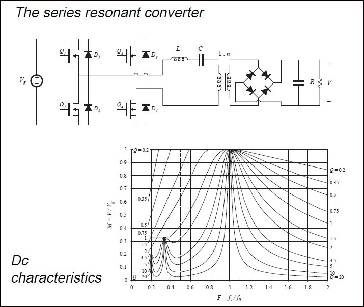
15.7 Introduction to LLC
- Resonant tank
- Resonance
- Soft switching
- ZVS
- High-frequency operation
MODULE 16 — Rectifiers and AC-DC Conversion
16.1 Diode Rectifier
- Half-wave
- Full-wave
- Bridge rectifier
16.2 Capacitor-Input Rectifier
- Charging pulses
- Ripple
- Peak current
16.3 Three-Phase Rectifier
- Six-pulse rectifier
- DC output
- Ripple frequency
16.4 Power Factor
- Displacement
- Distortion
- Harmonics
16.5 PFC Introduction
- Why PFC is required
- Boost PFC
- CCM PFC
- Interleaved PFC
MIT's power-electronics curriculum similarly treats rectifiers, power factor, DC/DC converters and magnetics as core foundations before moving into more advanced converter topics.
MODULE 17 — DC-AC Inverters
17.1 Single-Phase Half-Bridge
17.2 Single-Phase Full-Bridge
17.3 PWM Inverter
- Sinusoidal PWM
- Carrier waveform
- Modulation index
17.4 Dead Time
- Why it is required
- Cross-conduction
- Dead-time distortion
17.5 Three-Phase Inverter
- Six-switch bridge
- Switching states
- Phase voltage
- Line voltage
17.6 Applications
- Motor drives
- Solar inverters
- UPS
- EV traction
MODULE 18 — Switching Transients, Snubbers & Protection
18.1 Why Switching Creates Ringing
- PCB parasitic inductance
- Device capacitance
- Loop area
18.2 MOSFET Turn-On/Turn-Off
18.3 Voltage Overshoot
18.4 RCD Snubber
18.5 RC Snubber
18.6 TVS Protection
18.7 Gate Resistor
18.8 Active Gate Control
Practical laboratory
Measure:
- VDS
- VGS
- Drain current
- Overshoot
- Ringing
MODULE 19 — Thermal Management
19.1 Where Does Heat Come From?
- Semiconductor conduction loss
- Switching loss
- Magnetic loss
- Capacitor loss
19.2 Thermal Resistance
- Junction
- Case
- Heatsink
- Ambient
19.3 Heatsinks
19.4 Forced-Air Cooling
19.5 PCB Thermal Design
19.6 Junction Temperature
Practical exercise
Calculate the expected junction temperature of a MOSFET.
MODULE 20 — Gate Drivers
20.1 Why Gate Drivers Are Required
20.2 Low-Side Gate Drive
20.3 High-Side Gate Drive
20.4 Bootstrap Driver
20.5 Isolated Gate Driver
20.6 Gate Resistance
20.7 Miller Effect
20.8 Shoot-Through
20.9 Dead Time
20.10 SiC/GaN Gate Driving
MODULE 21 — Feedback & Control Fundamentals
21.1 Open Loop vs Closed Loop
21.2 Voltage Feedback
21.3 Error Amplifier
21.4 PWM Controller
21.5 Voltage-Mode Control
21.6 Current-Mode Control
21.7 Compensation
- Type I
- Type II
- Type III
21.8 Loop Stability
- Gain
- Phase
- Crossover frequency
- Phase margin
21.9 Introduction to Bode Plots
MODULE 22 — EMI & EMC Fundamentals
This would be particularly valuable as a NextGenBright practical engineering module, because students can connect converter switching behaviour directly to real EMC problems.
22.1 What Is EMI?
- Conducted EMI
- Radiated EMI
22.2 Noise Sources
- dv/dt
- di/dt
- Switching nodes
- Gate-drive loops
22.3 Common-Mode Noise
22.4 Differential-Mode Noise
22.5 Current Return Paths
22.6 PCB Layout
- High-current loops
- Gate-drive loop
- Ground planes
- Power/ground separation
22.7 EMI Filters
- Common-mode choke
- Differential-mode filter
- X capacitor
- Y capacitor
22.8 Practical EMC Debugging
- Near-field probes
- LISN
- Spectrum analyser
- Current probes
MODULE 23 — Simulation with LTspice
Students learn to simulate:
- Buck converter
- Boost converter
- Buck-boost
- Flyback
- Full-bridge inverter
- Gate driver
- Snubber
- LC filter
- Transformer
- LLC converter
Simulation skills
- Transient analysis
- AC analysis
- Parameter sweep
.step.meas- Efficiency calculation
- Waveform measurement
- FFT
- Bode plots
MODULE 24 — Practical Power Electronics Design
Students complete a complete converter design.
Design flow
Specification → Topology → Switching device → Magnetics → Capacitors → Gate driver → Thermal → PCB → Simulation → Testing
Students learn how engineers actually approach a design rather than simply solving equations.