Fundamentals of Analogue Electronics
🎯 What you'll get
MODULE 1 — Introduction to Analogue Electronics
1.1 What is Analogue Electronics?
- What is an analogue signal?
- Continuous voltage and current
- Analogue vs digital
- Real-world analogue signals
- Why analogue electronics is still important
1.2 Examples of Analogue Systems
- Audio systems
- Sensors
- Microphones
- Temperature measurement
- Power supplies
- Motor control
- RF systems
- Instrumentation
- Battery monitoring
1.3 Analogue Signal Chain
Students learn the concept:
Physical quantity → Sensor → Signal conditioning → Amplification → Filtering → ADC → Digital system
Online activity
Students identify analogue signals in:
- Temperature sensors
- Audio
- Light
- Battery voltage
- Pressure sensors
MODULE 2 — Voltage, Current & Resistance
2.1 Voltage
- Potential difference
- Voltage sources
- Ground/reference
2.2 Current
- Conventional current
- Electron flow
- Current direction
2.3 Resistance
- Resistance
- Conductors
- Insulators
- Resistor ratings
2.4 Ohm's Law
- Voltage
- Current
- Resistance
- Practical calculations
Interactive simulation
Students change:
Voltage → Resistance → Current
and observe the circuit response.
MODULE 3 — Electrical Power & Energy
Topics
- Electrical power
- Power dissipation
- Energy
- Resistor power rating
- Heat generation
Practical calculations
Students determine whether a resistor is suitable for a circuit.
Example
Voltage → Resistor → Current → Power
Online simulation
Change the resistor value and observe:
- Current
- Power
- Voltage
MODULE 4 — Series & Parallel Circuits
Series circuits
- Voltage division
- Current flow
- Equivalent resistance
Parallel circuits
- Current division
- Equivalent resistance
Voltage divider
- Basic divider
- Loaded divider
- Divider applications
Current divider
- Basic concept
Practical applications
- Sensor interfaces
- Reference voltages
- Bias networks
Virtual experiment
Design a:
5 V → voltage divider → 2.5 V output
and investigate what happens when a load is connected.
MODULE 5 — Kirchhoff's Laws & Circuit Analysis
5.1 Kirchhoff's Current Law – KCL
- Current entering
- Current leaving
- Node analysis
5.2 Kirchhoff's Voltage Law – KVL
- Voltage around a loop
- Voltage drops
- Voltage sources
5.3 Basic Circuit Analysis
- Nodes
- Branches
- Loops
Online exercises
Students analyse simple circuits using:
- KCL
- KVL
- Ohm's law
MODULE 6 — Capacitors
6.1 What is a Capacitor?
- Electric field
- Charge storage
- Capacitance
6.2 Capacitor Types
- Ceramic
- Electrolytic
- Film
6.3 Charging & Discharging
- Time behaviour
- RC time constant
6.4 Capacitors in Circuits
- DC blocking
- Filtering
- Decoupling
- Energy storage
6.5 Series & Parallel Capacitors
Virtual experiment
Use an oscilloscope simulation to observe:
Capacitor charging and discharging curves.
MODULE 7 — Inductors
7.1 What is an Inductor?
- Magnetic field
- Energy storage
- Inductance
7.2 Inductor Behaviour
- DC
- AC
- Current changes
7.3 RL Circuits
- Time constant
- Charging/discharging behaviour
7.4 Inductor Applications
- Filters
- Energy storage
- Transformers
- DC-DC converters
- Motor systems
Virtual experiment
Observe an RL transient using a simulated oscilloscope.
MODULE 8 — RC, RL & RLC Circuits
RC Circuits
- Low-pass behaviour
- High-pass behaviour
- Time constant
RL Circuits
- Transient response
- Filtering
RLC Circuits
- Resonance
- Damping
- Frequency response
Concepts
- Cut-off frequency
- Resonant frequency
- Bandwidth
- Q factor introduction
Online simulation
Students sweep frequency and observe circuit response.
MODULE 9 — Diodes
9.1 Semiconductor Basics
- Silicon
- Semiconductor concept
- PN junction
9.2 Diode Operation
- Forward bias
- Reverse bias
- Forward voltage
- Reverse current
9.3 Diode I-V Characteristic
- Forward region
- Reverse region
- Breakdown
9.4 Diode Models
- Ideal diode
- Constant-voltage model
- Practical model
9.5 Diode Types
- Signal diode
- Power diode
- Schottky diode
- Zener diode
- LED
- Photodiode
Virtual experiment
Plot the:
Diode I-V characteristic
and identify different operating regions.
MODULE 10 — Diode Applications
Rectification
- Half-wave rectifier
- Full-wave rectifier
- Bridge rectifier
Filtering
- Capacitor smoothing
- Ripple voltage
Zener regulation
- Voltage reference
- Basic voltage regulation
Clipping
- Positive clipper
- Negative clipper
Clamping
- DC restoration
Peak detector
Practical online project
Build a Virtual DC Power Supply
AC → Rectifier → Capacitor → Regulator → DC output
MODULE 11 — Transistors Introduction
Why Transistors?
- Electronic switching
- Amplification
- Signal processing
- Power control
BJT
- NPN
- PNP
MOSFET
- NMOS
- PMOS
Comparison
- BJT vs MOSFET
- Current-controlled vs voltage-controlled concepts
Applications
- Amplifiers
- Switches
- Drivers
- Power electronics
MODULE 12 — BJT Fundamentals
Topics
- Base
- Collector
- Emitter
- NPN operation
- PNP operation
Operating regions
- Cutoff
- Active
- Saturation
BJT as a switch
BJT as an amplifier
Current gain
- β concept
- Collector current
- Base current
Virtual experiment
Students change base current and observe collector current.
MODULE 13 — MOSFET Fundamentals
MOSFET structure
- Gate
- Drain
- Source
- Body
Types
- NMOS
- PMOS
- Enhancement mode
- Depletion mode introduction
MOSFET operation
- Cutoff
- Linear/ohmic region
- Saturation region
Key parameters
- Threshold voltage
- RDS(on)
- Gate charge
- Drain current
Applications
- Digital switching
- Analog circuits
- Motor control
- Power conversion
Online simulation
Students plot:
Gate voltage → Drain current
and investigate MOSFET behaviour.
MODULE 14 — Transistor Biasing
This is a key analogue-electronics topic.
Why bias a transistor?
- Establish operating point
- Linear operation
- Stable amplification
Topics
- Q-point
- DC operating point
- Bias voltage
- Bias current
BJT biasing
- Fixed bias
- Voltage-divider bias
- Emitter resistor
MOSFET biasing
- Gate bias
- Source resistor
Practical simulation
Students select resistor values to establish a required transistor operating point.
MODULE 15 — Small-Signal Amplifiers
15.1 What is an Amplifier?
- Voltage gain
- Current gain
- Power gain
15.2 Common BJT Amplifier Configurations
- Common emitter
- Common collector
- Common base
15.3 MOSFET Amplifiers
- Common source
- Common drain
- Common gate
Important parameters
- Gain
- Input impedance
- Output impedance
- Bandwidth
Virtual oscilloscope
Students observe:
Input waveform → Amplifier → Output waveform
MODULE 16 — Frequency Response of Amplifiers
Topics
- Gain vs frequency
- Low-frequency response
- Mid-band gain
- High-frequency response
- Bandwidth
Cut-off frequencies
- Lower cut-off
- Upper cut-off
-3 dB point
Practical investigation
Students perform a frequency sweep and generate an amplifier response curve.
MODULE 17 — Feedback in Analogue Electronics
What is feedback?
- Positive feedback
- Negative feedback
Negative feedback
- Gain stability
- Bandwidth
- Distortion reduction
- Noise effects
- Input/output impedance
Positive feedback
- Oscillators
- Switching
- Hysteresis
Practical example
Compare an amplifier:
Without feedback vs with feedback
using simulation.
MODULE 18 — Operational Amplifiers
One of the most important modules in the course.
18.1 What is an Op-Amp?
- Differential input
- Output
- Power supplies
18.2 Ideal Op-Amp
- Infinite gain
- High input impedance
- Low output impedance
18.3 Real Op-Amp
- Offset
- Bias current
- Gain-bandwidth
- Slew rate
- Output limitations
MODULE 19 — Basic Op-Amp Circuits
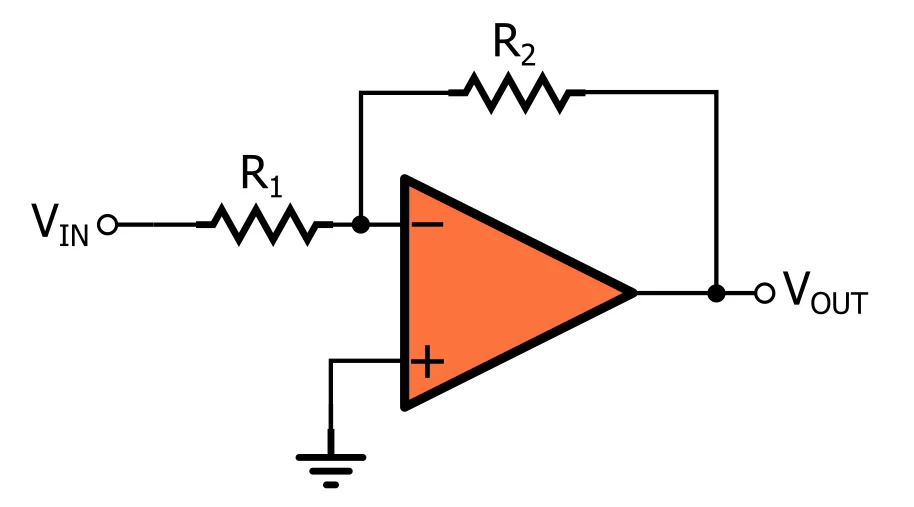
Inverting amplifier
- Gain
- Phase inversion
Non-inverting amplifier
- Gain
- Phase
Voltage follower
- Buffer
Summing amplifier
- Multiple inputs
Differential amplifier
- Difference between two signals
Comparator
Virtual experiments
Students change resistor values and observe the output gain.
MODULE 20 — Advanced Op-Amp Applications
Integrator
Differentiator
Active rectifier
Peak detector
Precision amplifier
Instrumentation amplifier
Practical applications
- Sensor interfaces
- Audio
- Instrumentation
- Battery measurement
- Signal conditioning
MODULE 21 — Comparators & Schmitt Triggers
Comparator
- Threshold
- Reference
- Output switching
Hysteresis
- Upper threshold
- Lower threshold
Schmitt trigger
- Noise immunity
- Signal cleaning
Applications
- Sensor threshold detection
- Zero-crossing
- Switch debouncing
- Waveform conversion
Online simulation
Students add noise to an input signal and compare:
Comparator vs Schmitt trigger
MODULE 22 — Analogue Filters
Why filters are needed
- Remove unwanted signals
- Reduce noise
- Select frequency ranges
Passive Filters
- RC low-pass
- RC high-pass
- RL filters
- RLC filters
Active Filters
- Active low-pass
- Active high-pass
- Band-pass
- Band-stop
Filter parameters
- Cut-off frequency
- Bandwidth
- Roll-off
- Q factor
Online frequency sweep
Students design a filter and verify its response using a simulated Bode plot.
MODULE 23 — Bode Plots & Frequency Response
Topics
- Magnitude response
- Phase response
- dB
- Frequency axis
- Cut-off frequency
- Gain
Reading Bode plots
Students learn to identify:
- Gain
- Bandwidth
- Poles
- Zeros introduction
- Roll-off
Practical simulation
Generate a Bode plot of an RC filter.
MODULE 24 — Oscillators & Waveform Generation
Why oscillators?
Generate:
- Sine waves
- Square waves
- Triangle waves
- Sawtooth waveforms
Topics
- Feedback
- Oscillation condition
- RC oscillators
- LC oscillators
- Crystal oscillator introduction
Applications
- Clocks
- Signal generators
- Communication systems
- MCU timing
Online simulation
Students change component values and observe oscillator frequency.
MODULE 25 — Power Supplies
This module connects analogue electronics to real hardware.
AC/DC conversion
- Transformer concept
- Rectifier
- Smoothing
- Regulation
Linear regulators
- Basic operation
- Dropout voltage
- Heat dissipation
LDO
- Low-dropout regulators
- Applications
Switching regulator introduction
- Buck
- Boost
- Buck-boost
Key concepts
- Efficiency
- Ripple
- Regulation
- Thermal considerations
MODULE 26 — Voltage References & Regulation
Topics
- Reference voltage
- Zener reference
- Bandgap reference introduction
- Linear regulation
- Load regulation
- Line regulation
Practical exercise
Design a simple:
5 V regulated supply
and investigate what happens when:
- Input voltage changes
- Load changes
MODULE 27 — Sensors & Analogue Signal Conditioning
Sensors
- Temperature
- Light
- Pressure
- Current
- Voltage
- Position
- Acceleration
Signal-conditioning chain
Sensor → Amplifier → Filter → ADC → MCU
Topics
- Sensor output
- Offset
- Gain
- Filtering
- Noise
- Level shifting
Practical example
Temperature sensor → Op-amp → ADC
MODULE 28 — Instrumentation Amplifiers
Topics
- Differential signals
- Common-mode voltage
- Common-mode rejection
- CMRR
- Instrumentation amplifier architecture
Applications
- Load cells
- Strain gauges
- Medical instrumentation
- Current measurement
- Precision sensors
Online simulation
Students apply a small differential signal with a large common-mode voltage and observe the output.
MODULE 29 — ADC & DAC Fundamentals
This creates a bridge between analogue and digital electronics.
ADC
- Sampling
- Quantisation
- Resolution
- Reference voltage
- Sampling frequency
DAC
- Digital input
- Analog output
- Resolution
ADC architectures
- Flash ADC
- SAR ADC introduction
- Sigma-delta introduction
Practical application
Analogue sensor → ADC → MCU
MODULE 30 — Noise in Analogue Electronics
Very important for students progressing toward professional electronics.
Noise sources
- Thermal noise
- Shot noise
- Flicker noise
- EMI introduction
- Supply noise
Signal-to-noise ratio
Noise reduction
- Filtering
- Shielding
- Grounding
- Decoupling
- Differential signalling
Practical simulation
Students add noise to a signal and investigate the effect of filtering.
MODULE 31 — Practical Analogue Circuit Design
Students learn the complete design process.
Design flow
Requirement
↓
Select topology
↓
Calculate component values
↓
Simulate
↓
Check waveform
↓
Check frequency response
↓
Check component stress
↓
Optimise
Design considerations
- Tolerance
- Temperature
- Loading
- Bandwidth
- Noise
- Power consumption
MODULE 32 — SPICE Simulation
This should be a major practical component of the online course.
Introduction to SPICE
- What is SPICE?
- Schematic entry
- Components
- Ground
- Sources
Simulation types
- DC operating point
- Transient analysis
- AC analysis
- Parameter sweep
Virtual instruments
- Multimeter
- Oscilloscope
- Function generator
- Bode plot
Students learn to simulate:
- Diode circuits
- Transistor amplifiers
- Op-amp circuits
- Filters
- Power supplies
MODULE 33 — Analogue Troubleshooting
Students are given simulated faulty circuits.
Fault examples
- Incorrect resistor
- Open connection
- Short circuit
- Incorrect bias
- Saturated amplifier
- Incorrect capacitor
- Wrong transistor orientation
- Excessive loading
Troubleshooting methodology
Expected behaviour → Measurement → Compare → Identify fault → Correct → Verify
This is particularly valuable for an online course because it replaces some of the diagnostic experience normally obtained in a physical laboratory.
MODULE 34 — Analogue Electronics in Real Products
Students see where the concepts are used.
Automotive
- Sensors
- Battery monitoring
- Current sensing
- Motor control
- ECU signal conditioning
Consumer Electronics
- Audio
- Cameras
- Smartphones
- Power supplies
Industrial
- Sensors
- Instrumentation
- PLC input circuits
Aerospace
- Sensor conditioning
- Power monitoring
- Instrumentation
- Control systems
Renewable Energy
- Solar monitoring
- Current/voltage measurement
- Power conversion
ONLINE PRACTICAL PROJECTS
Project 1 — Variable Voltage Sensor
Students create:
Potentiometer → Voltage divider → Measurement
Learn:
- Voltage division
- Loading
- Measurement
Project 2 — LED Light Sensor
Light sensor → Signal conditioning → LED
Learn:
- Sensor
- Voltage divider
- Transistor/op-amp
- Threshold
Project 3 — Audio Amplifier
Audio input → Op-amp/transistor amplifier → Output
Students investigate:
- Gain
- Distortion
- Frequency response
Project 4 — Active Low-Pass Filter
Design:
Input → RC/Op-amp filter → Output
Students specify a target cut-off frequency and verify it through simulation.
Project 5 — Temperature Signal Conditioner
Temperature sensor → Amplifier → Filter → ADC
Students design the analogue front end for a simulated MCU.
Project 6 — Regulated Power Supply
AC/DC source → Rectifier → Filter → Regulator → Load
Students investigate:
- Ripple
- Regulation
- Load changes